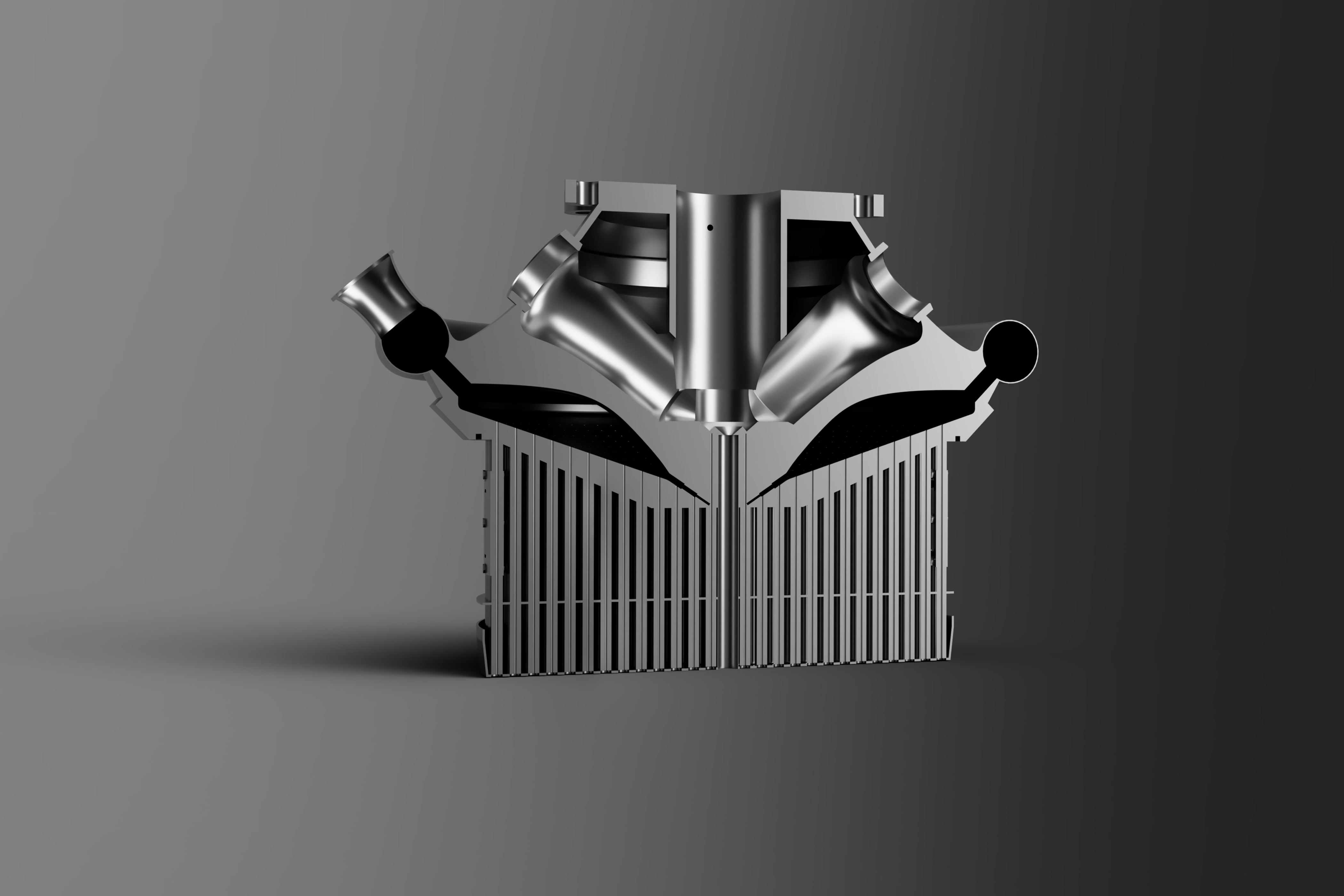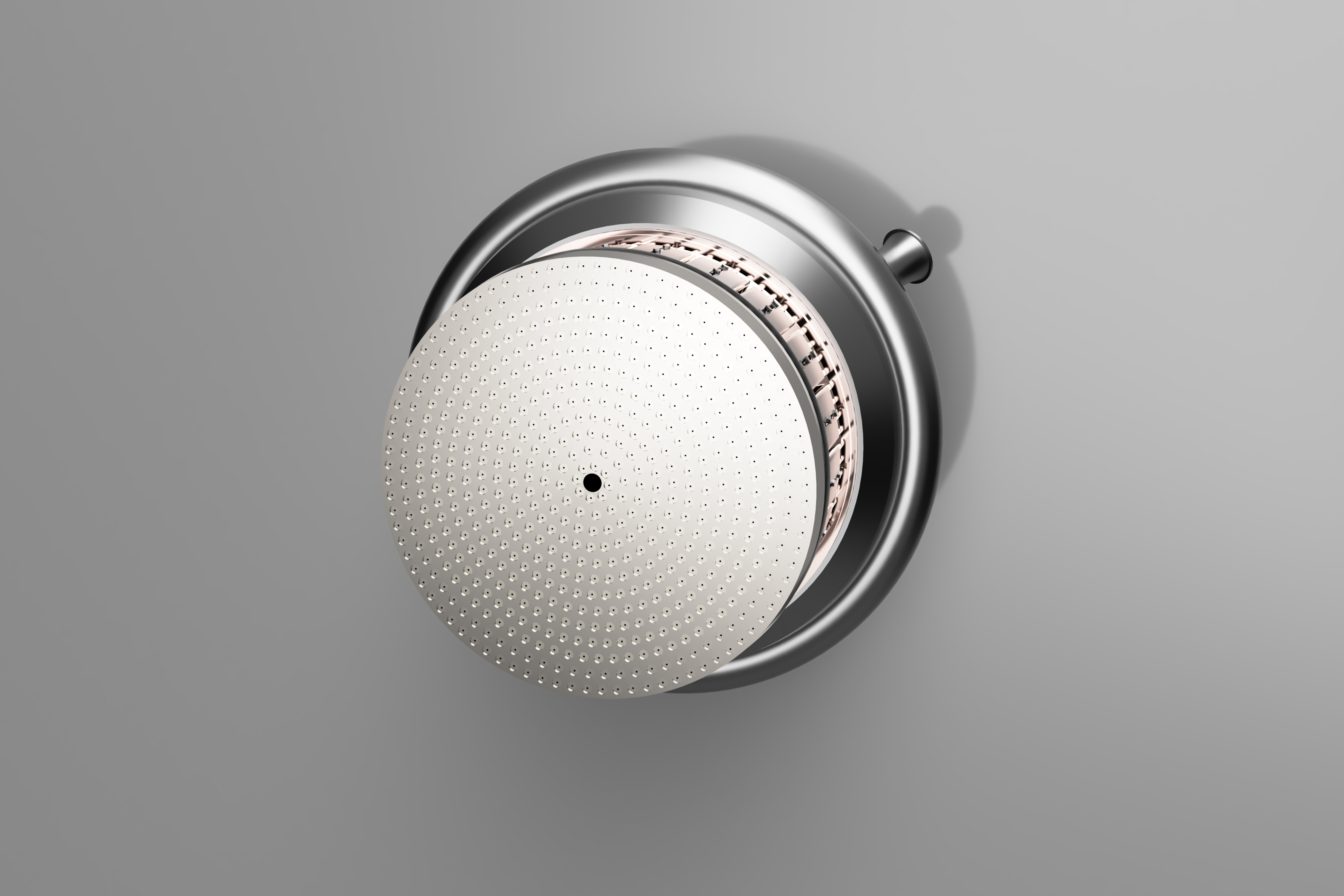
The Main Injector injects into the main combustion chamber a combination of hot, fuel-rich gas from two preburners, cold hydrogen gas from the cooling circuits, and cold liquid oxygen from the Turbopump
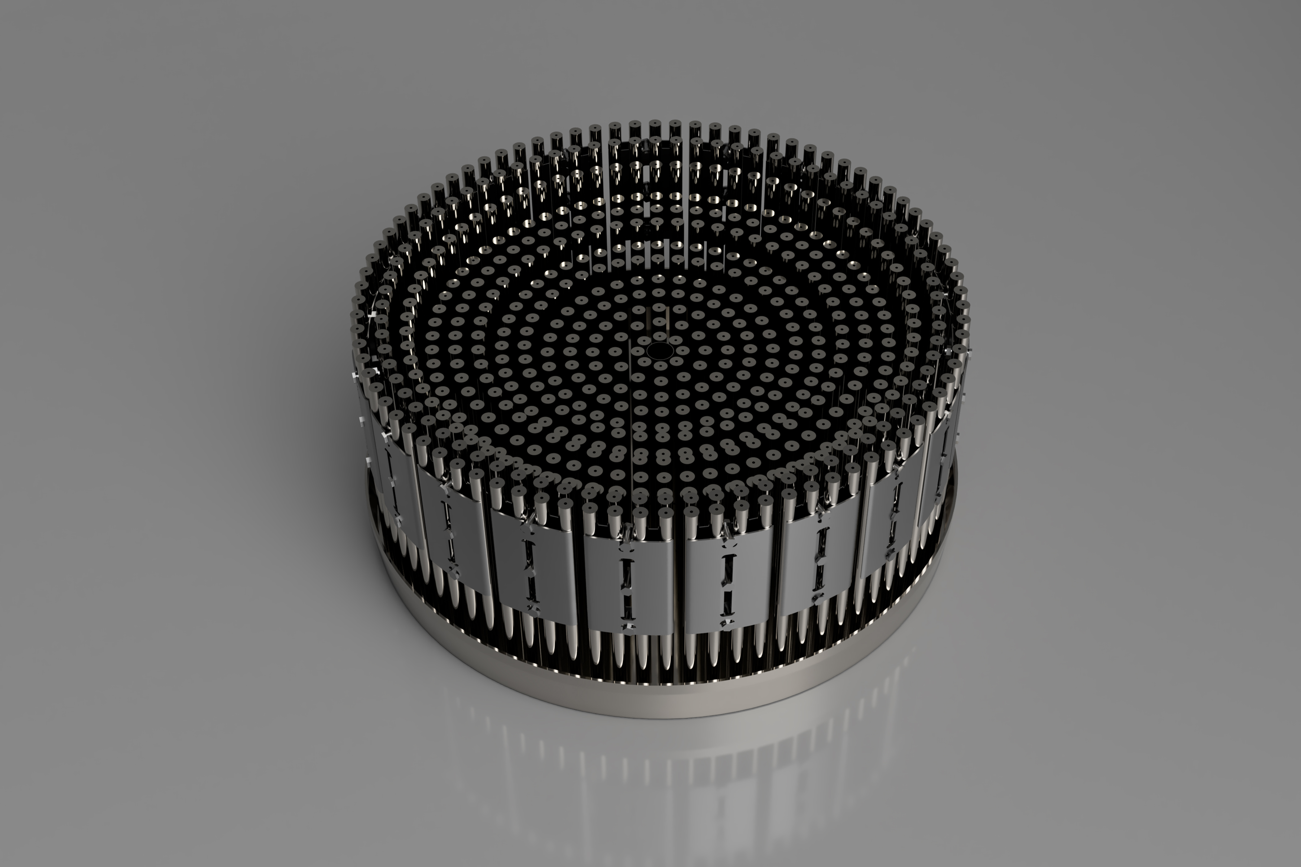
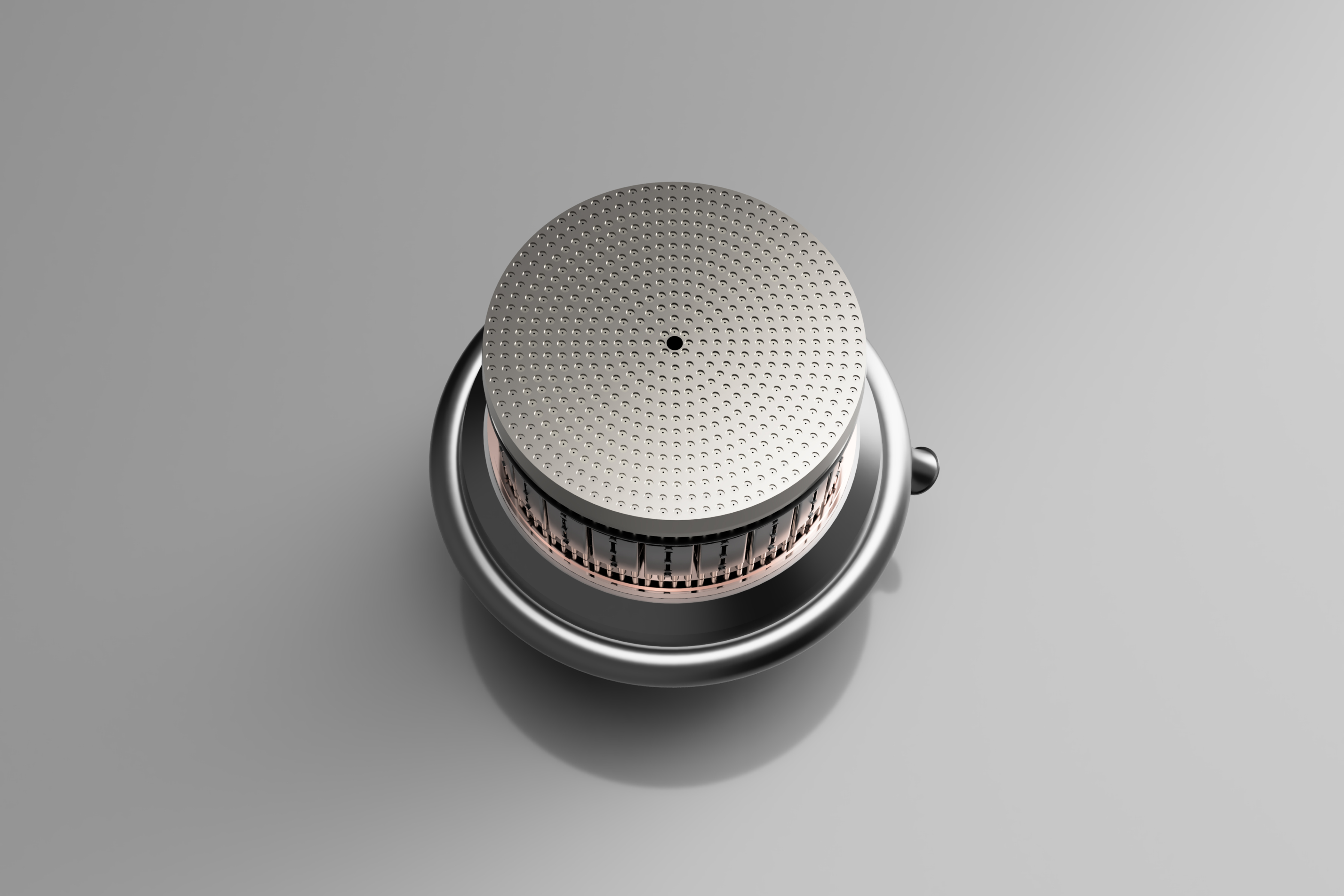
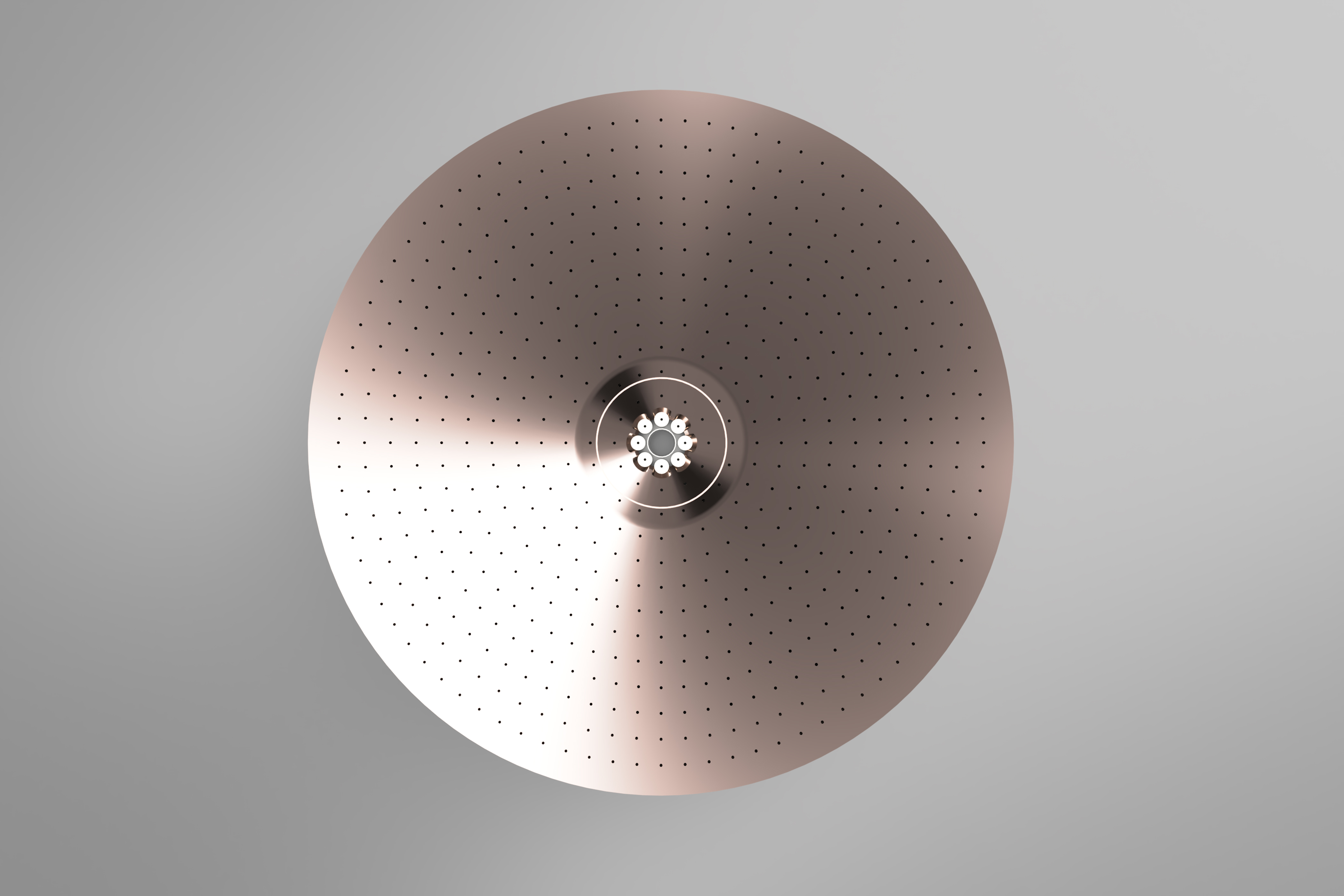
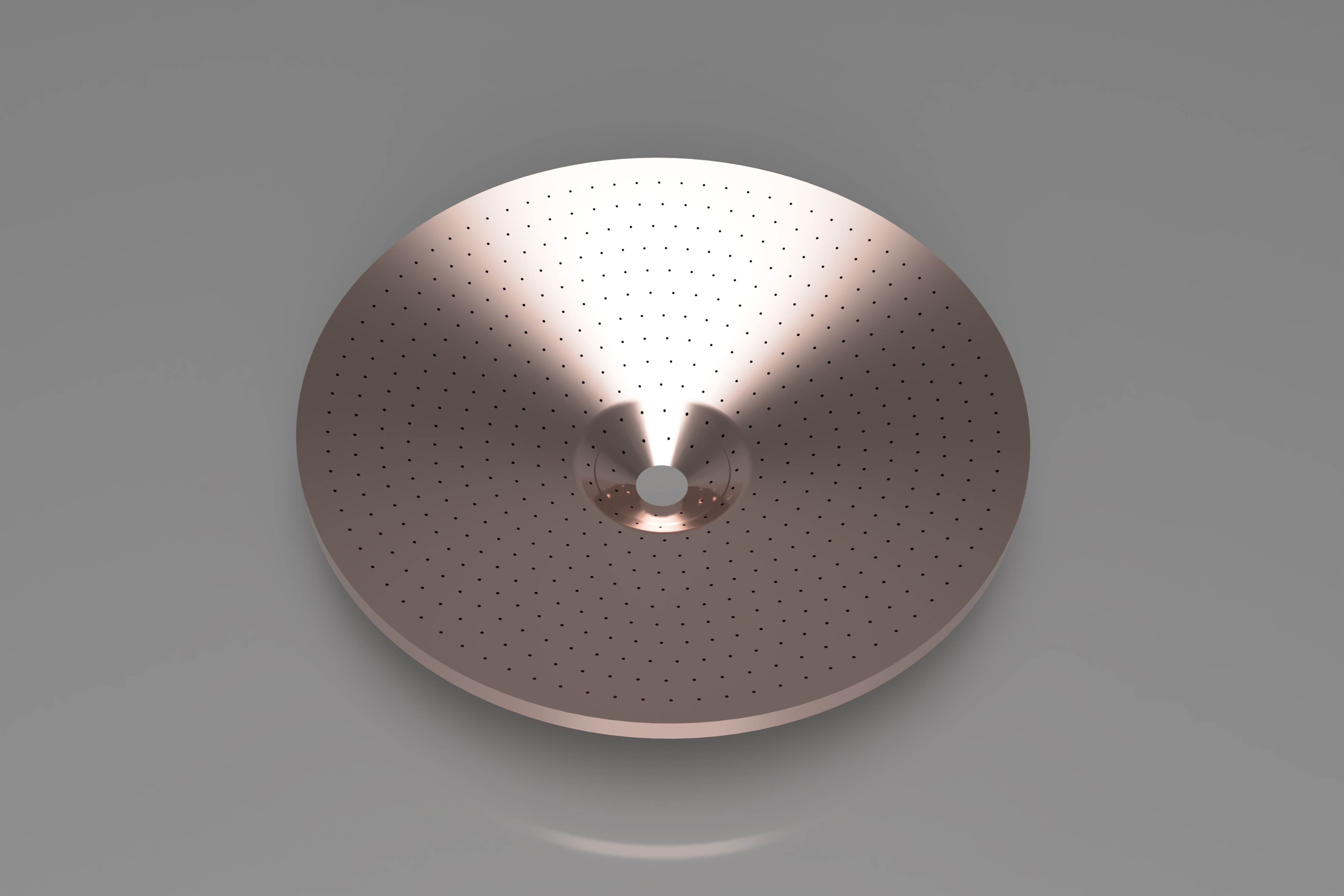
The injector includes 600 coaxial elements which inject liquid oxygen from the oxidizer manifold through their centre posts. Each element also injects, through its annulus, the hot, fuel-rich gas entering the cavity between the heat shield and the secondary plate.
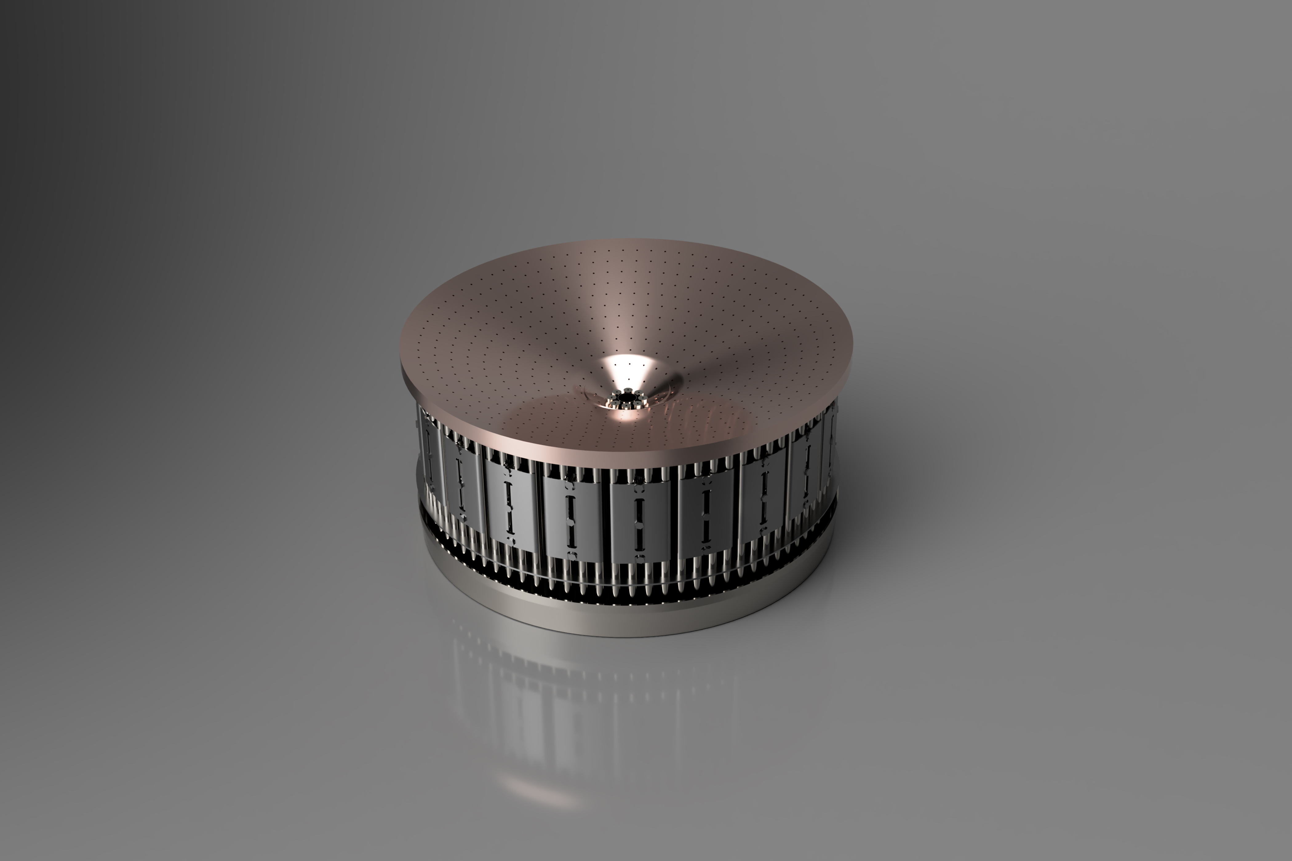
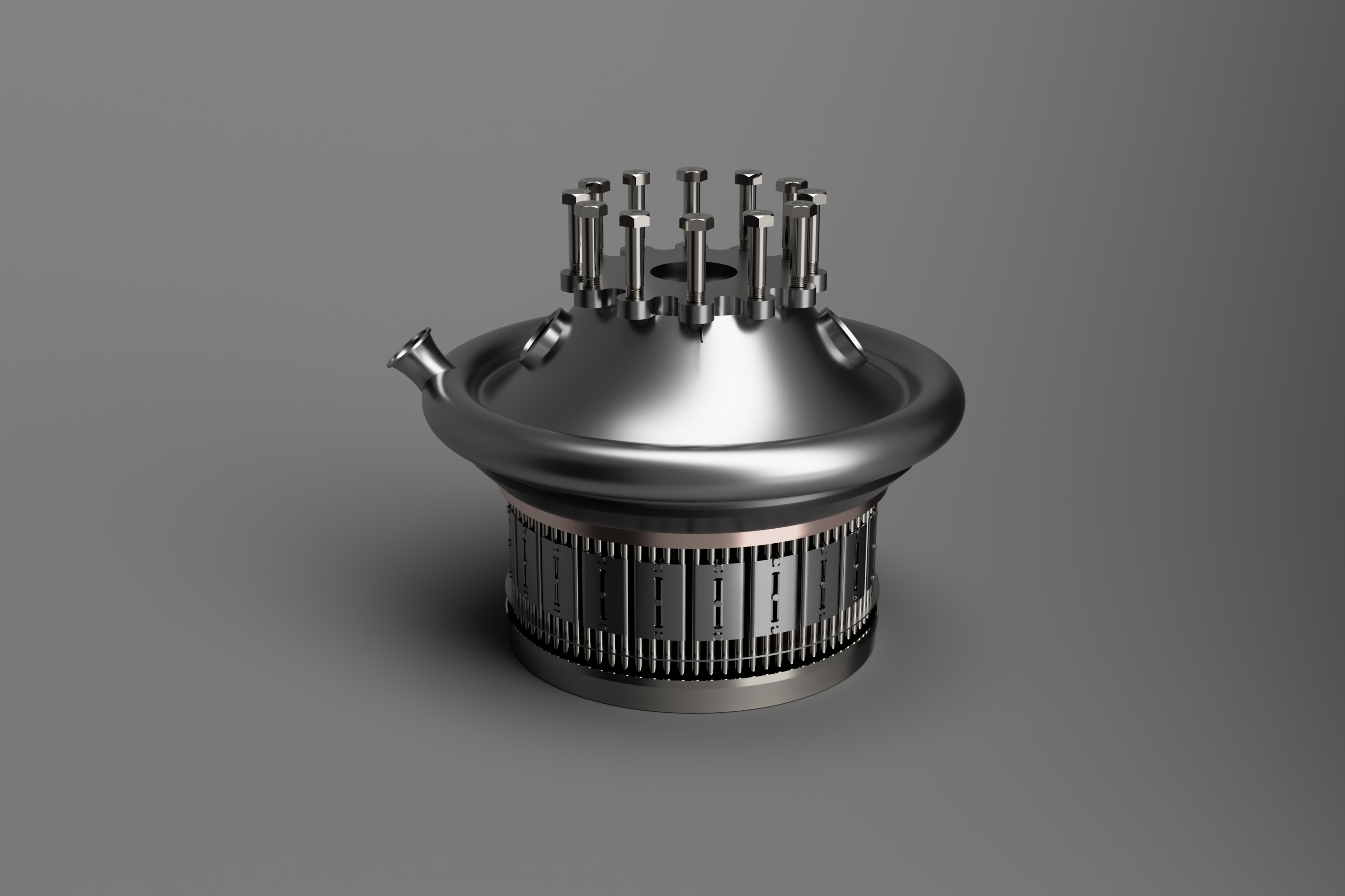
Cold hydrogen gas, that had previously migrated through the double walls of the HGM, enters the slot between the secondary plate and the lip of the primary plate. Both plates are porous and are transpiration-cooled by the cold hydrogen gas as it flows through them.
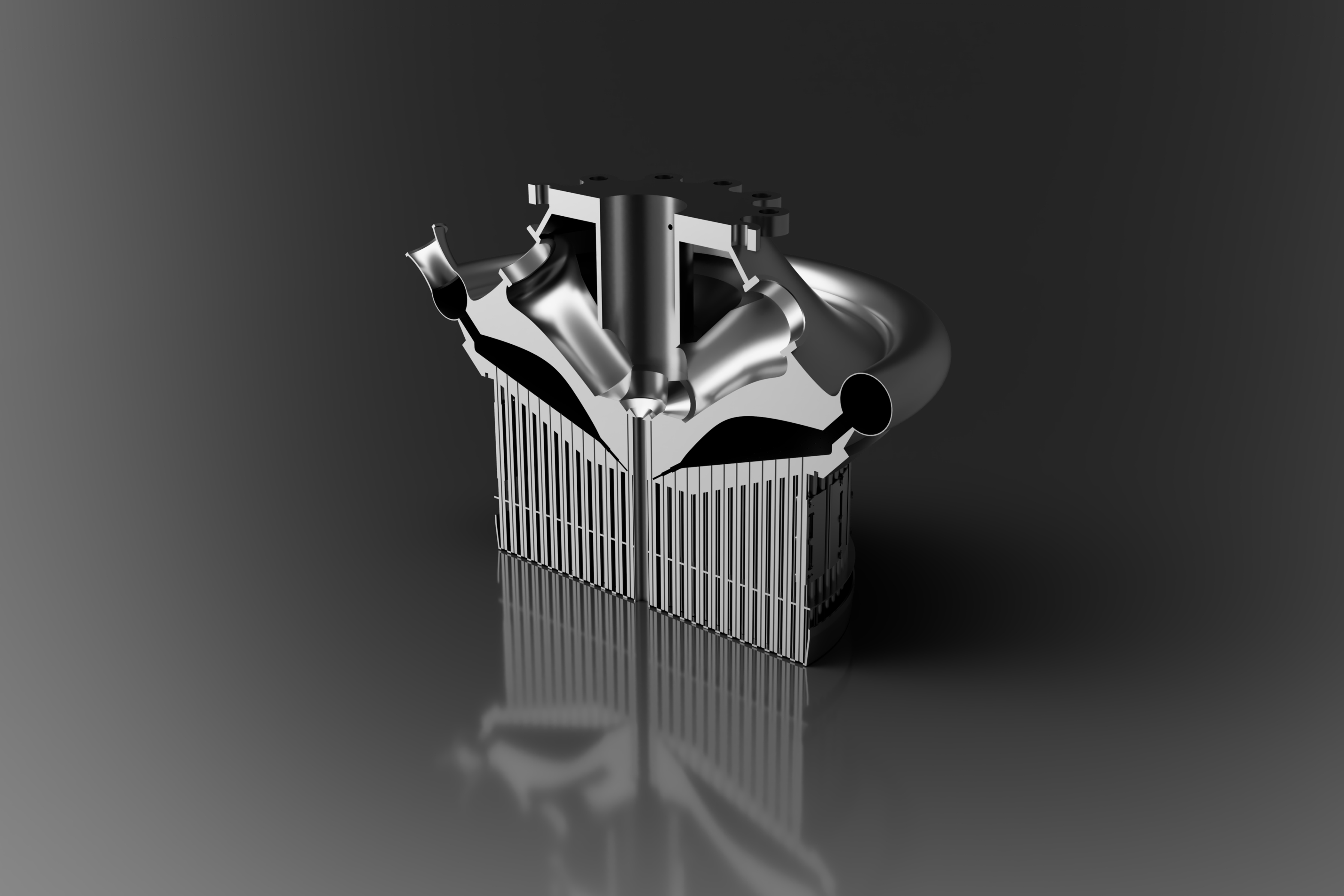
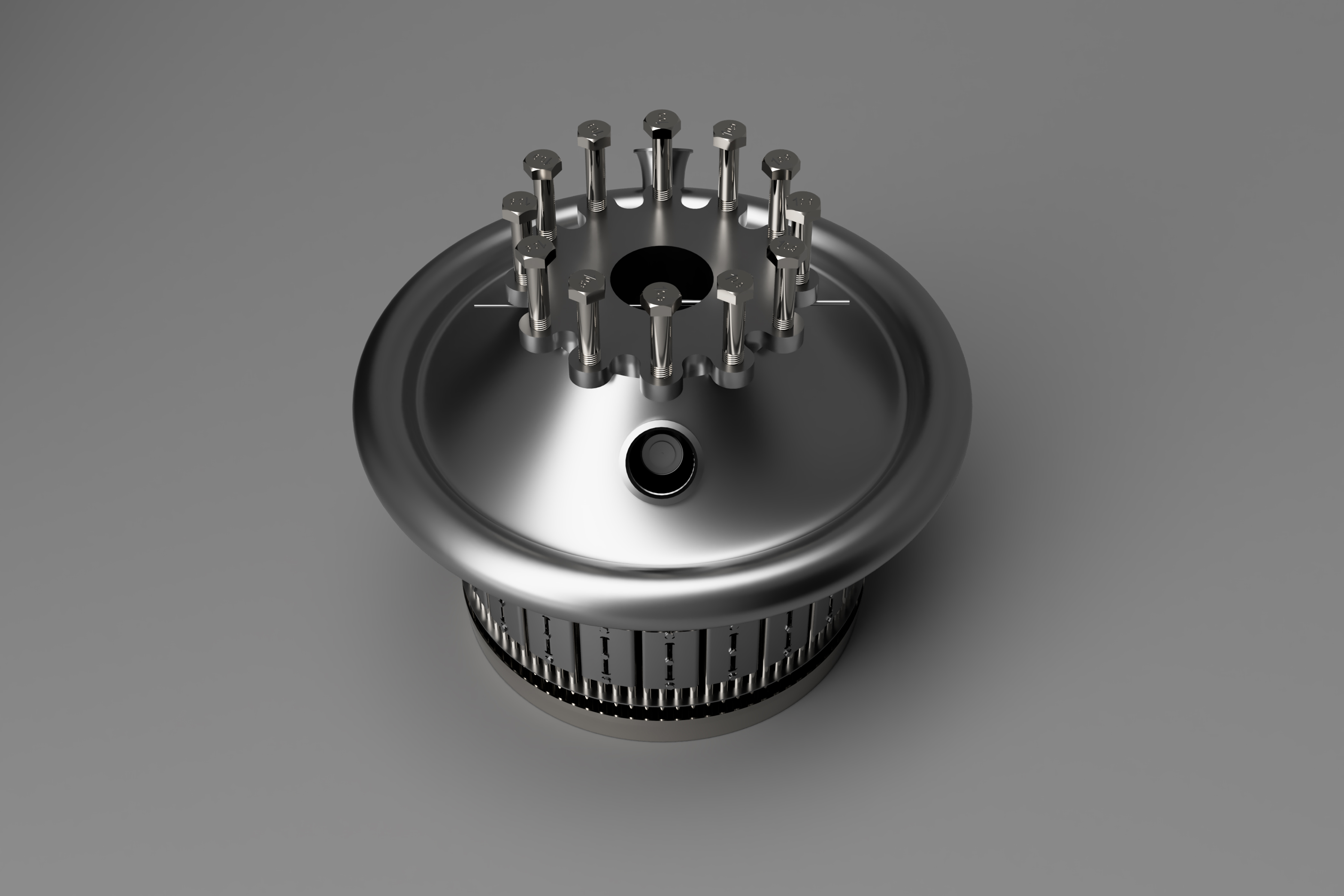
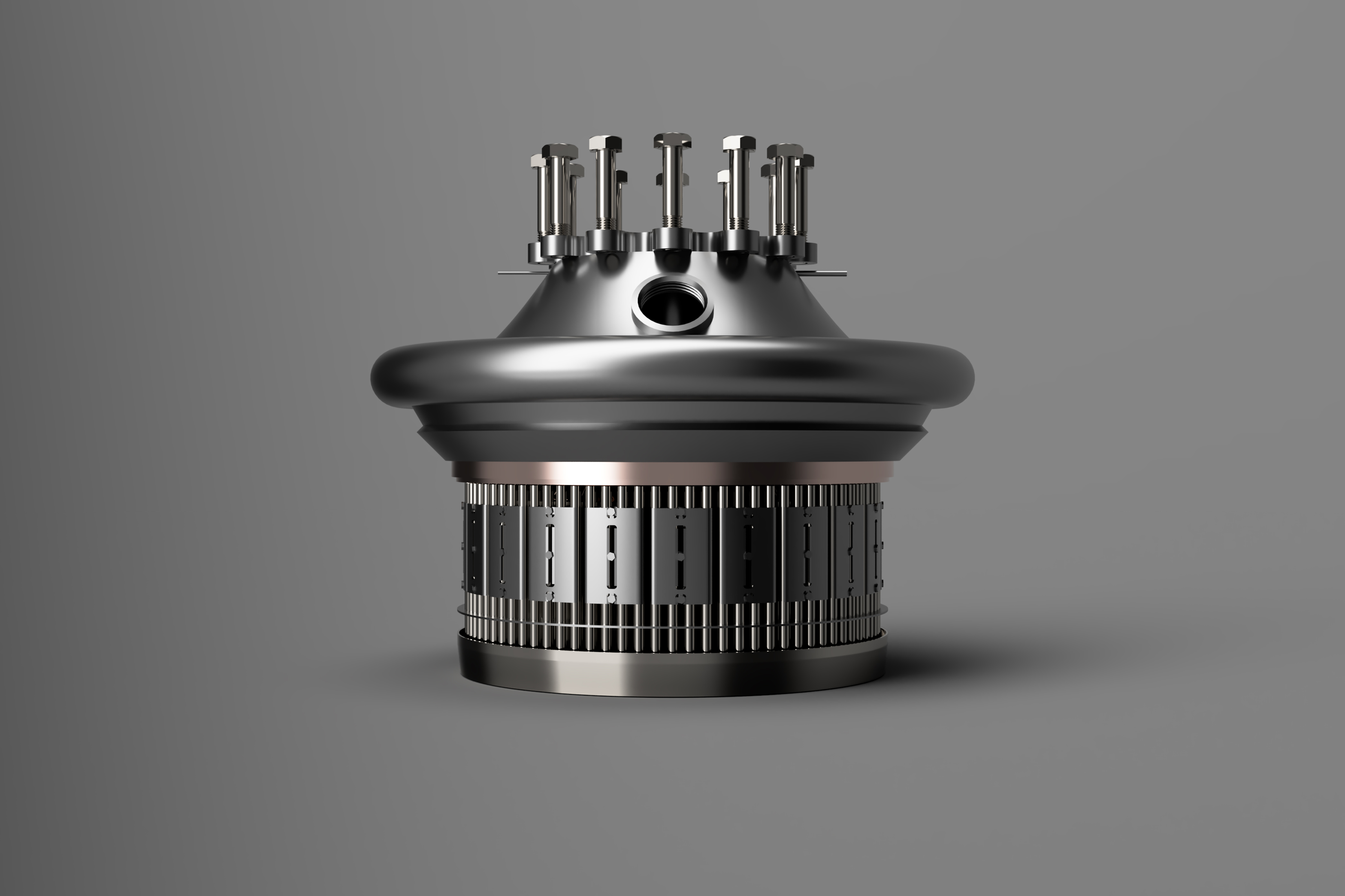
An augmented spark ignition (ASI) system is located in the centre of the injector. Small quantities of hydrogen and oxygen are continuously injected into this chamber, and initially ignited by two spark igniters.