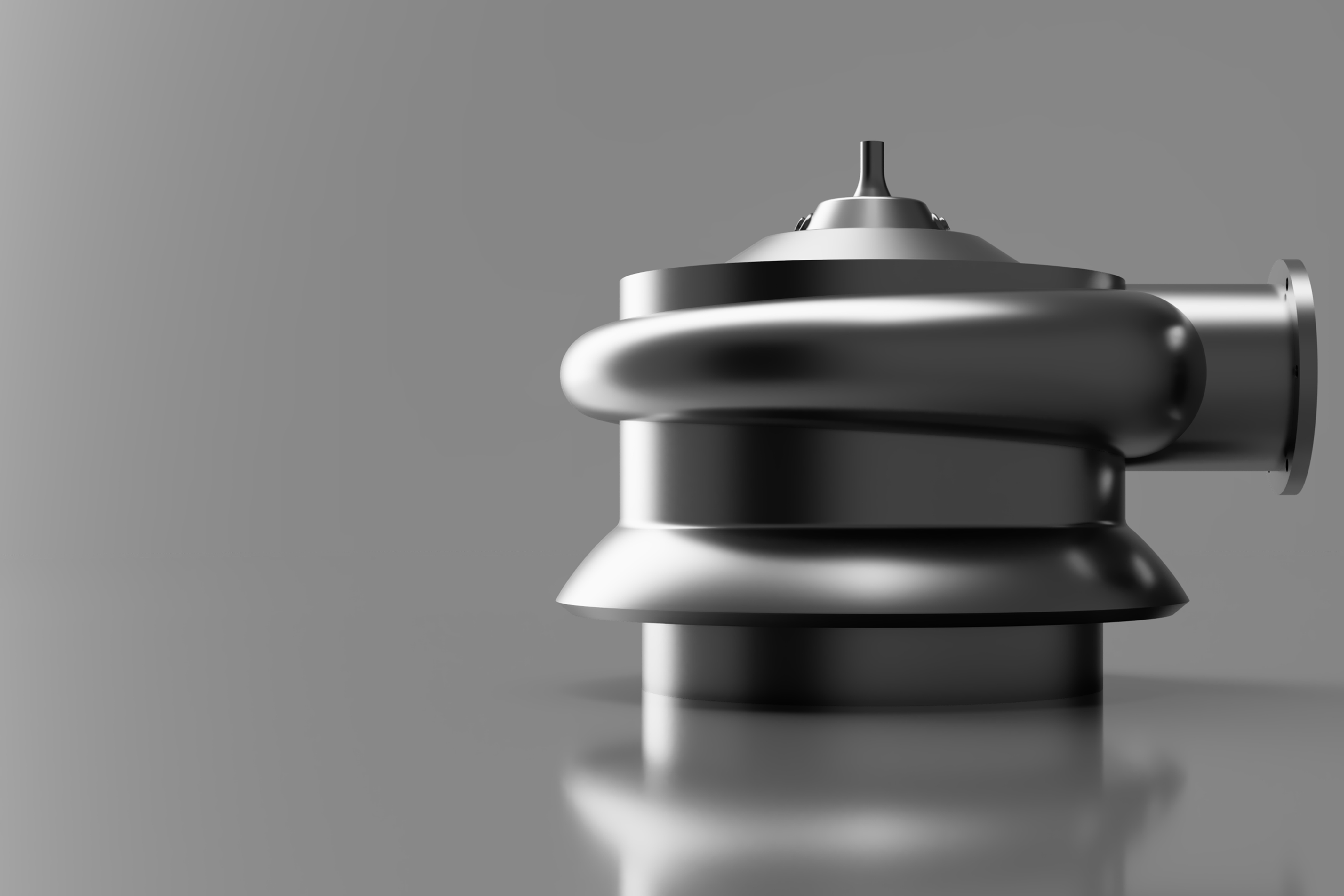
The fuel preburner combusts fuel and oxidizer at an extremely fuel-rich mixture ratio, and thus supplies hot gas to drive the high-pressure fuel turbopump.
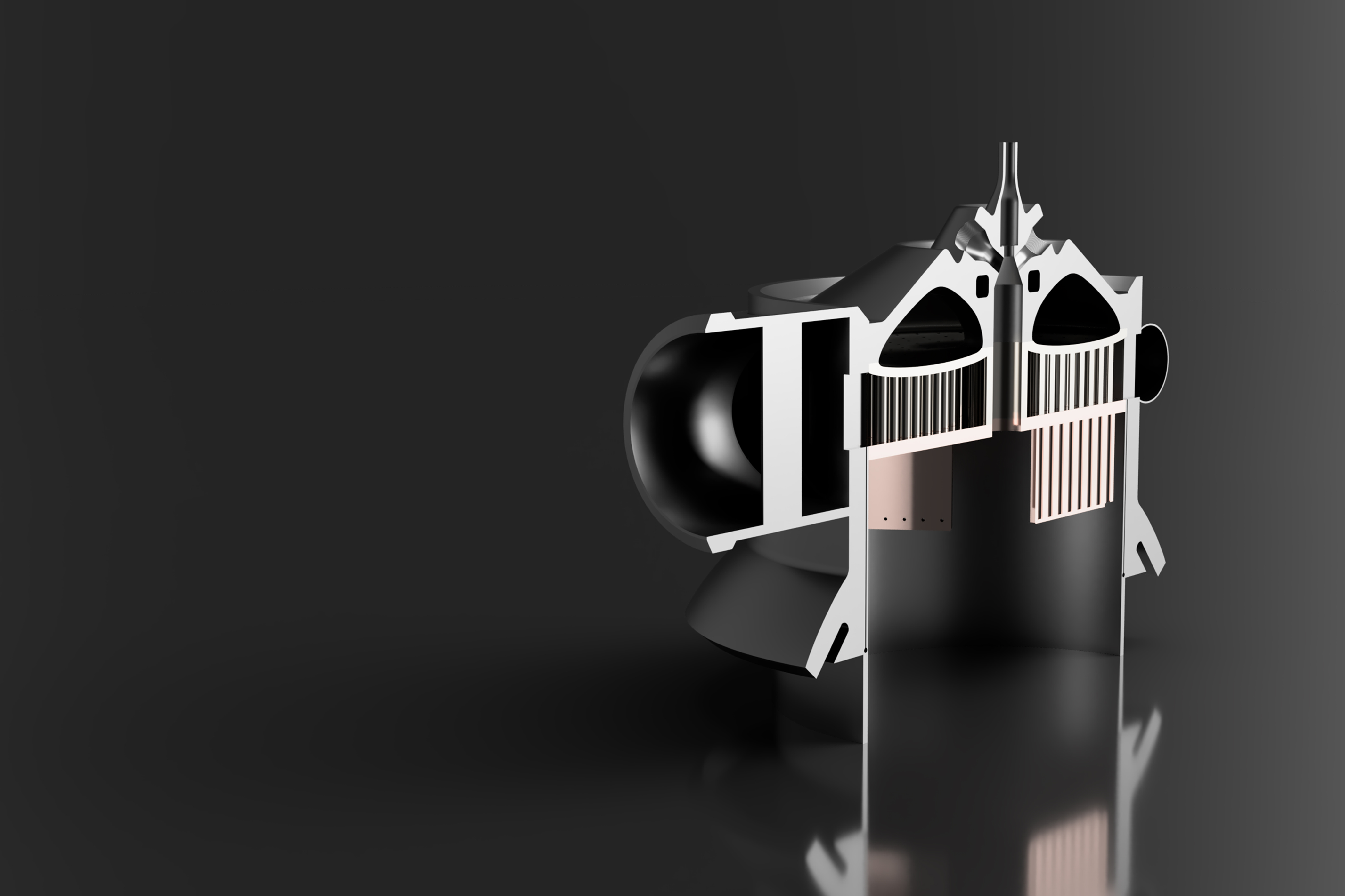
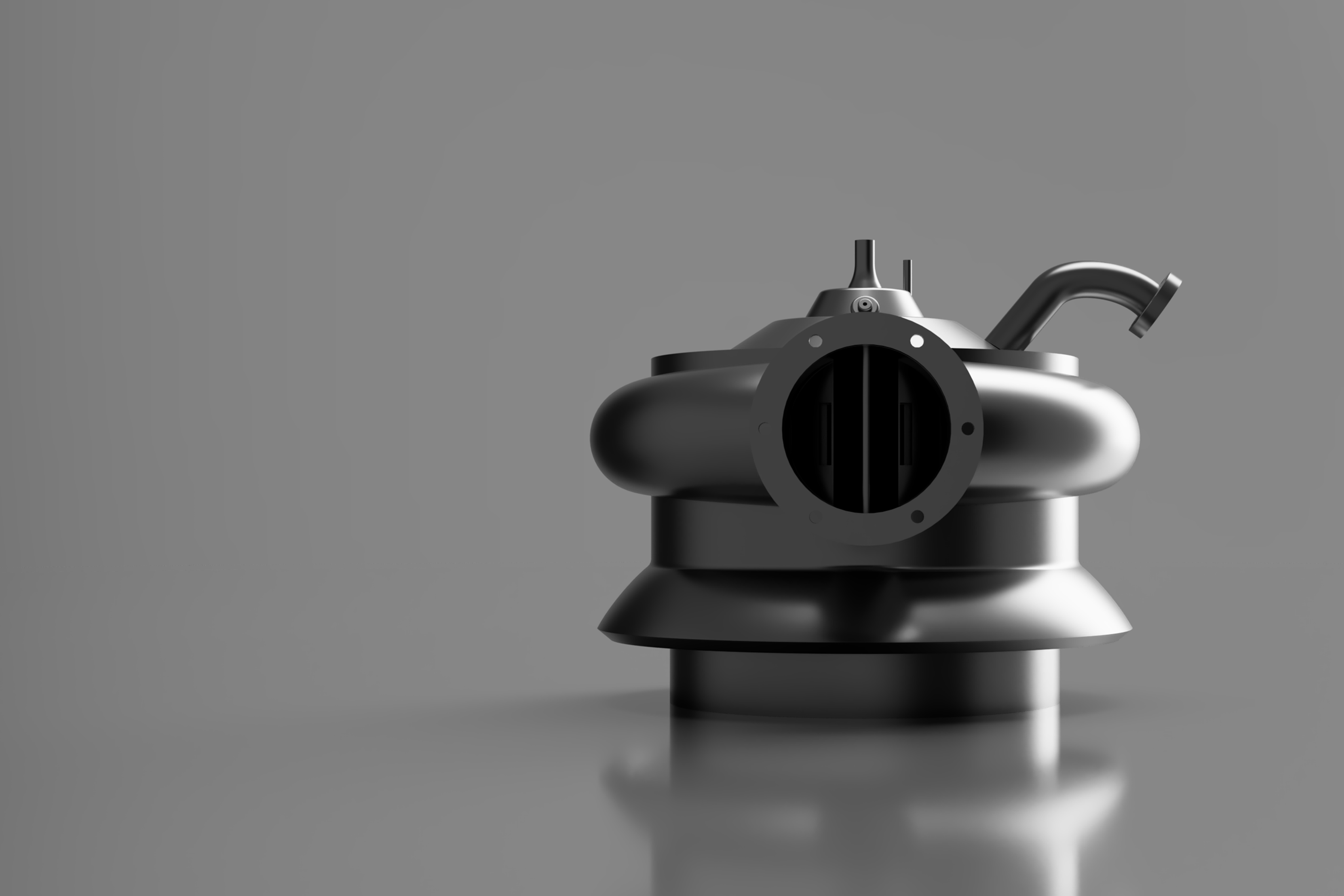
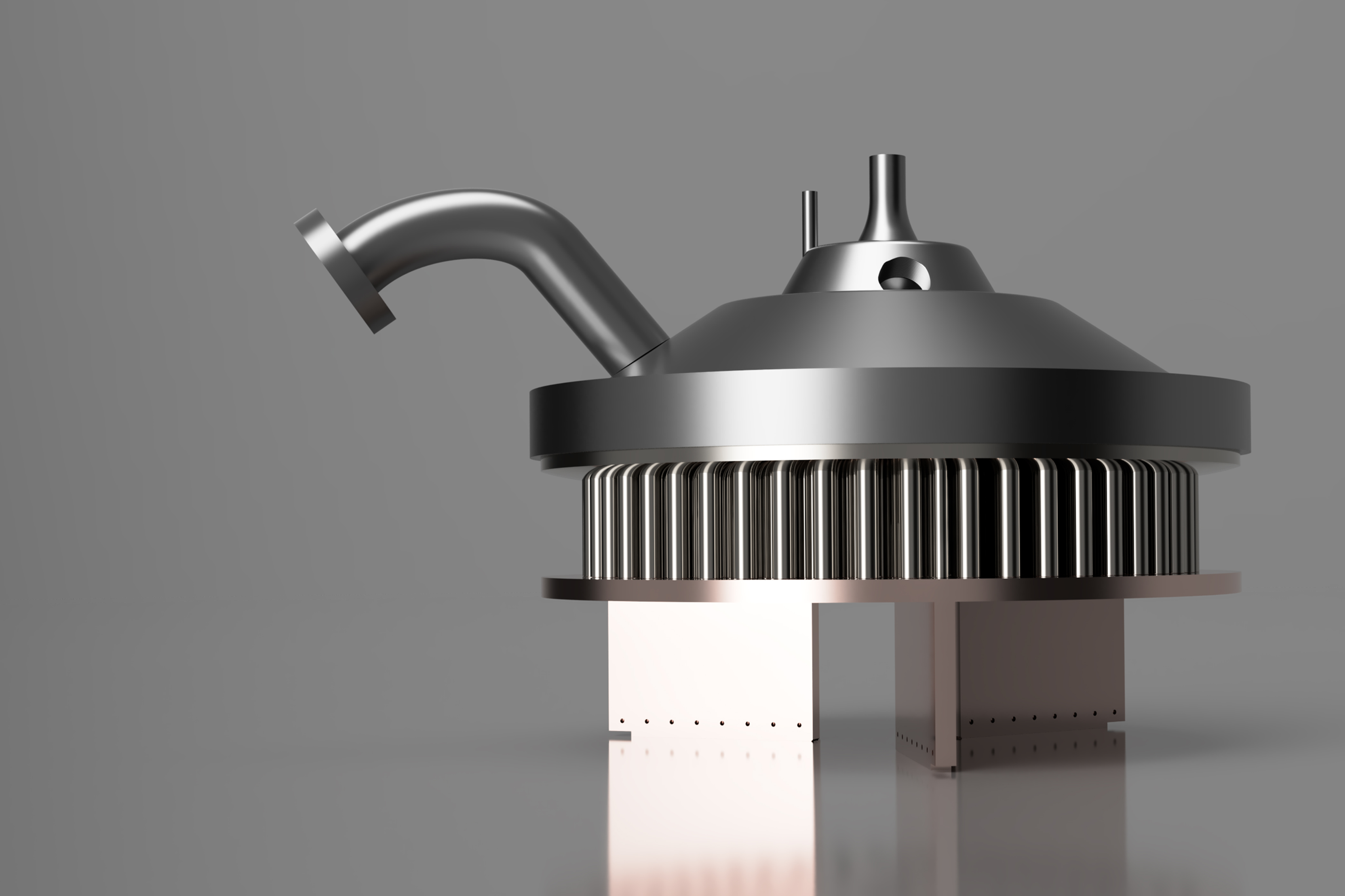
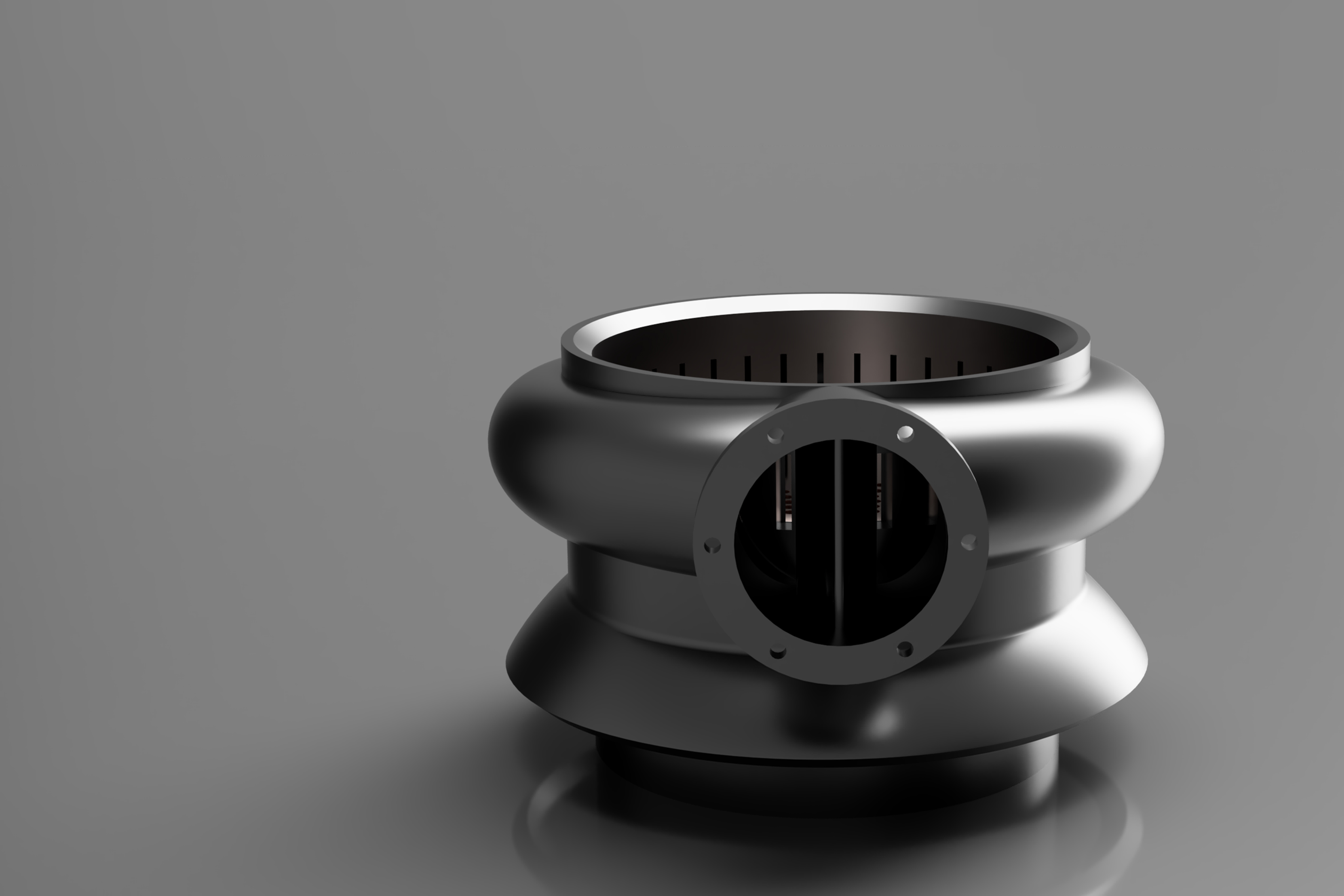
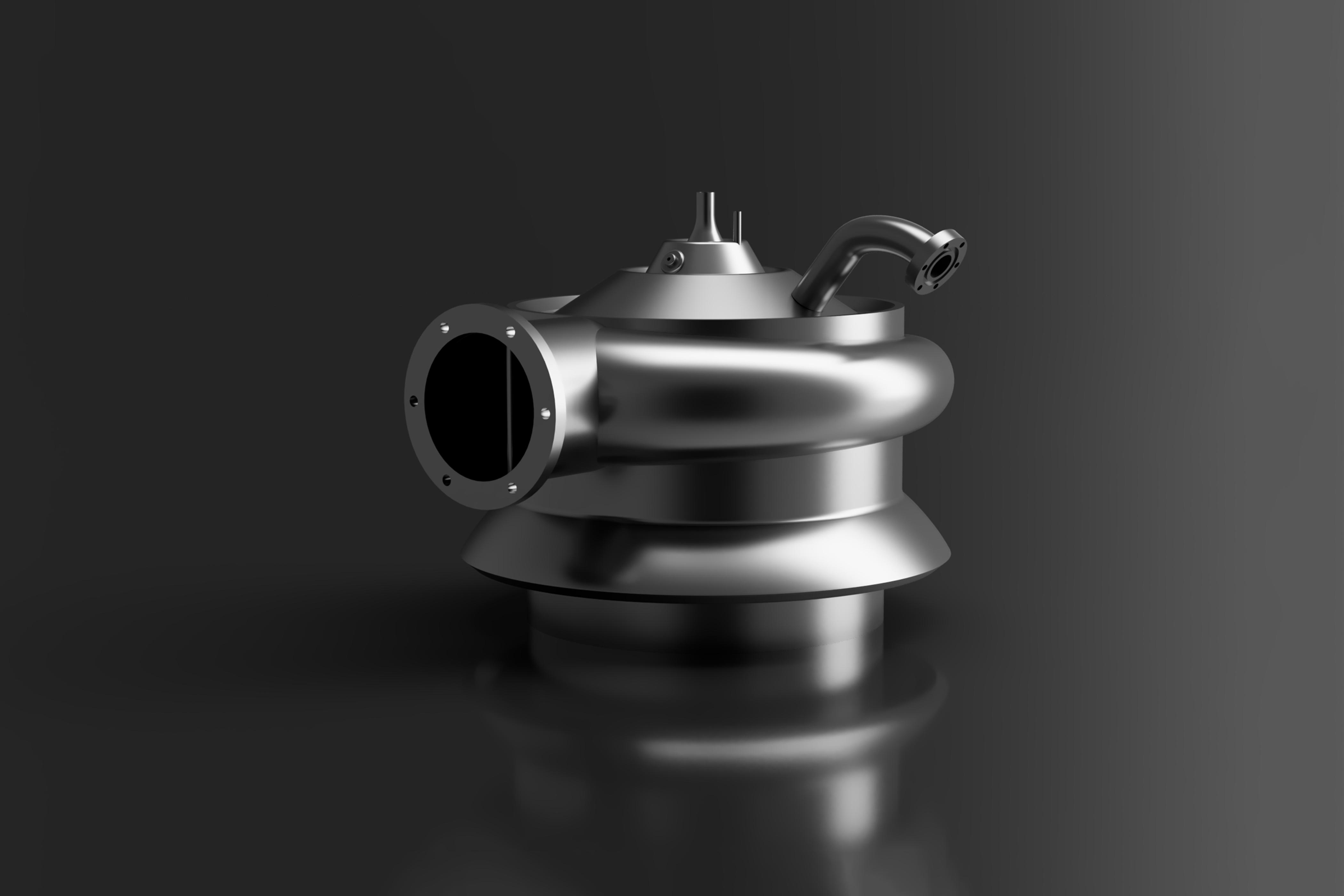
The FPB provides the hot gas for the HP Fuel Turbopump. It consists of two propellant manifolds, a centrally located spark igniters, an injector and a combustor chamber.
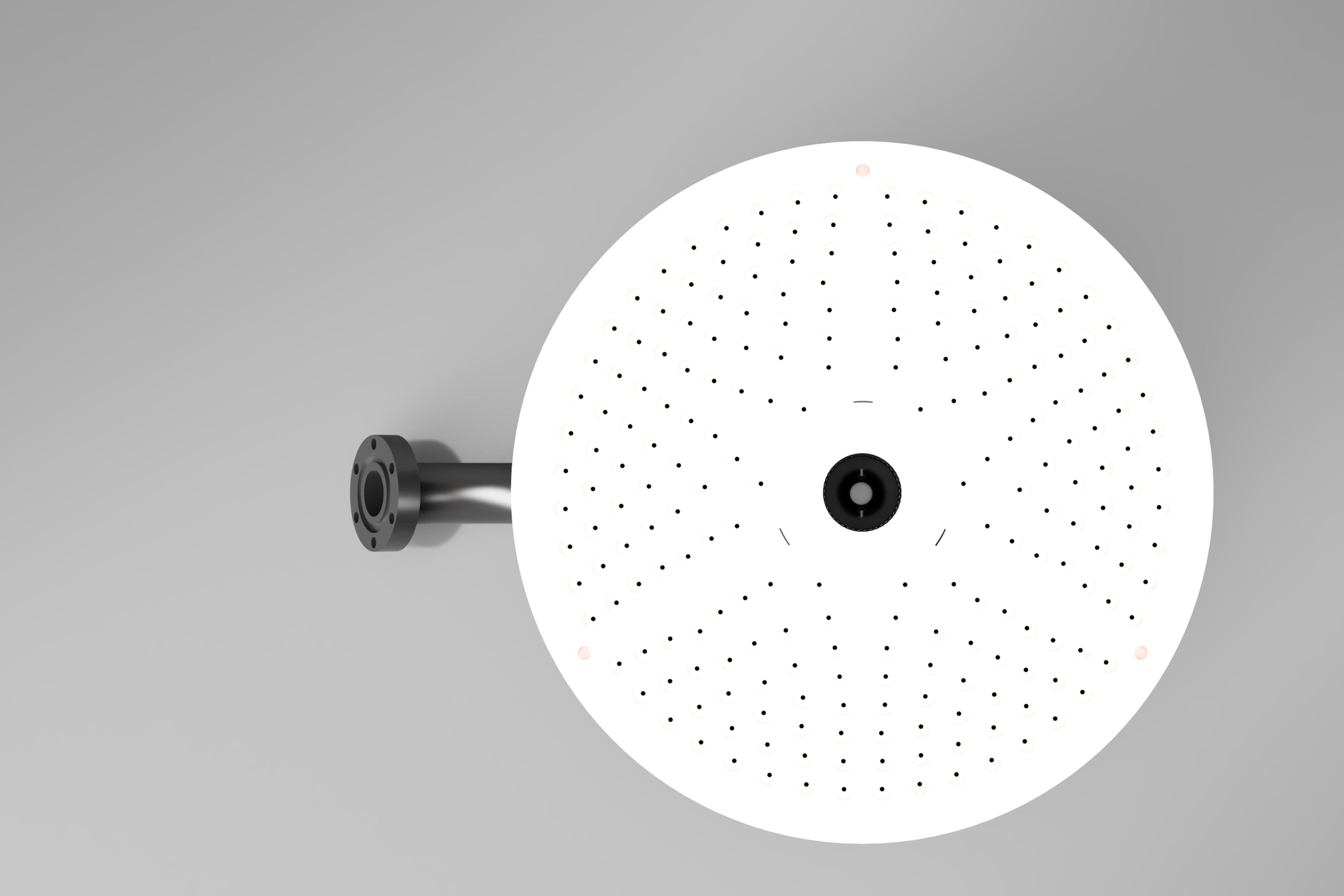
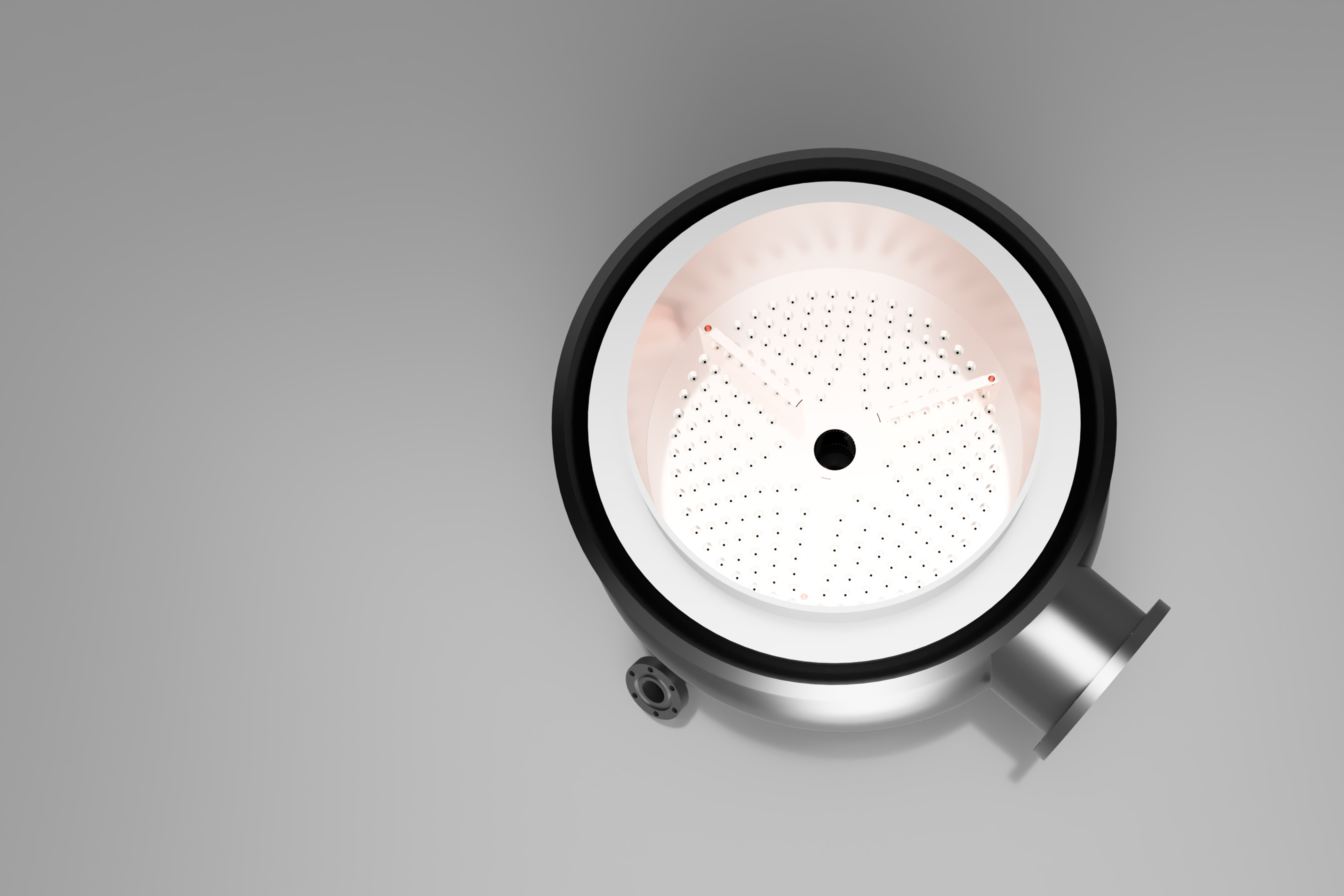
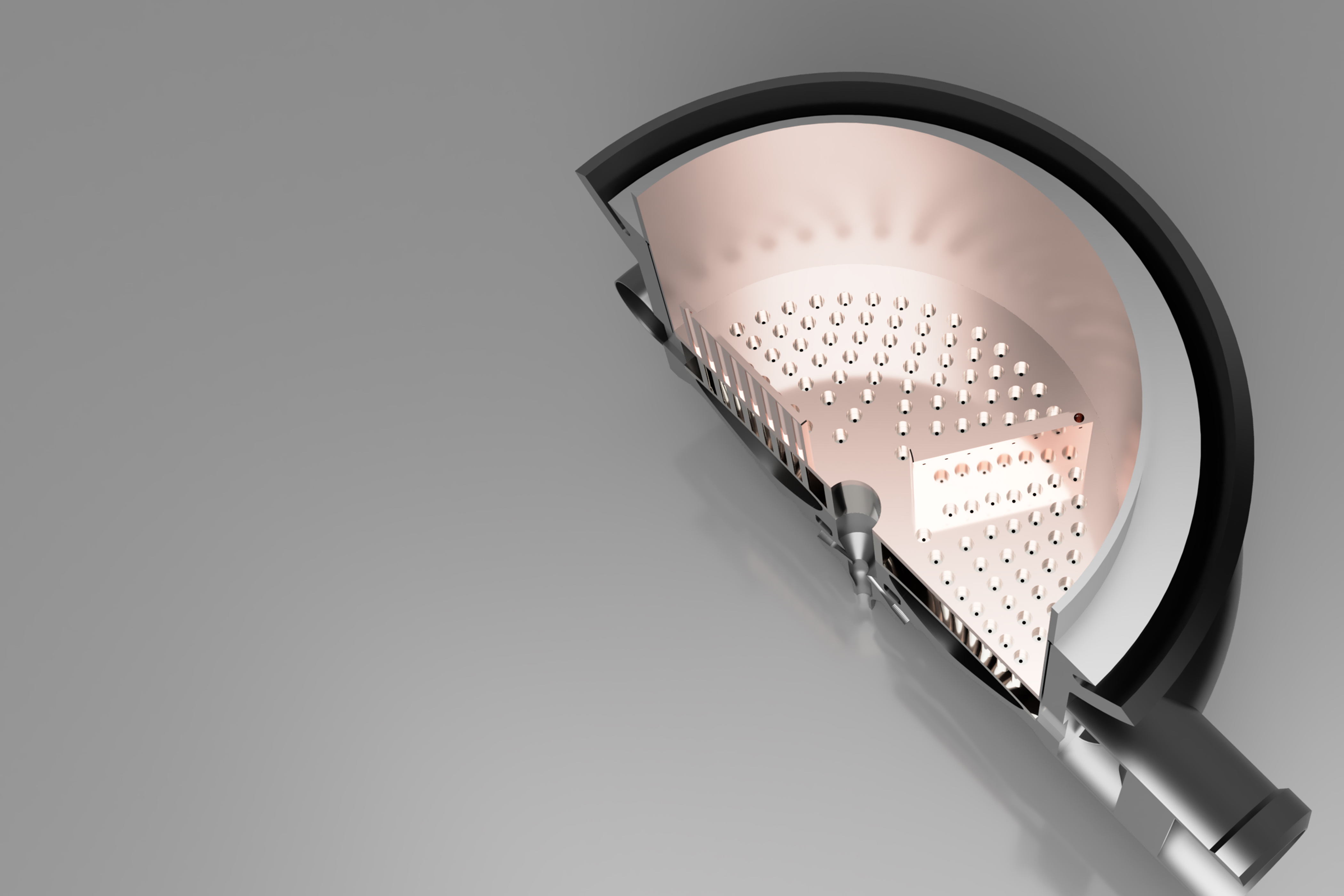
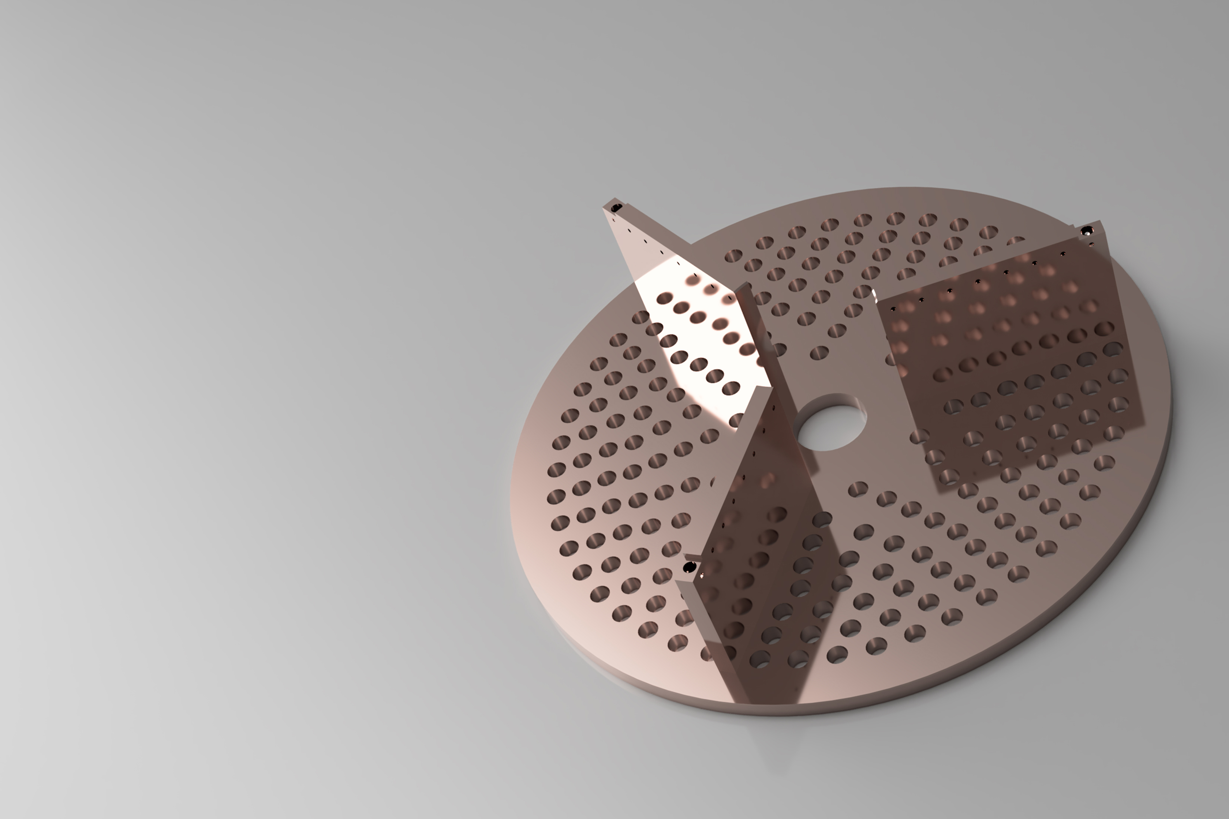
The FPB is made of 264 coaxial injection elements, arranged in a concentric row pattern. Each element having low velocity LOX flowing in a centre post, with high velocity gaseous hydrogen in a surrounding annulus to promote uniform mixing.
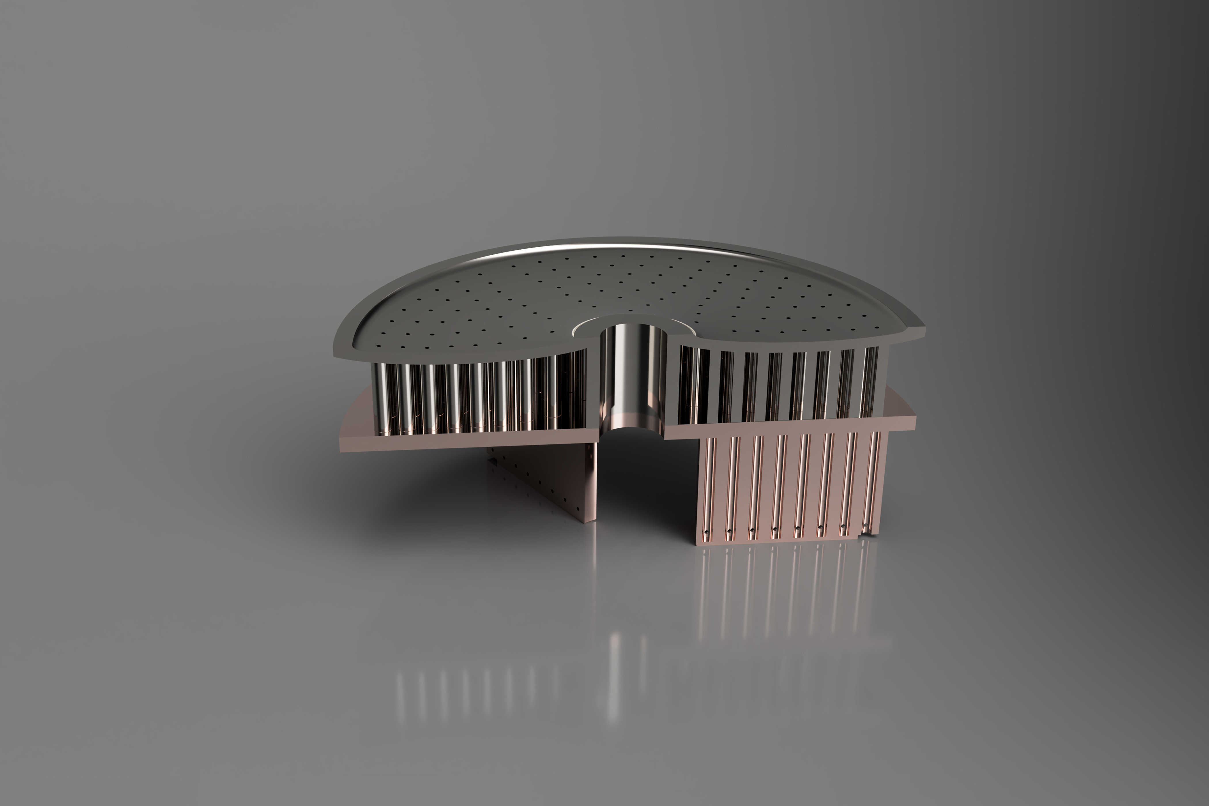
Combustion takes place below the faceplate in three compartments which are separated by 2.25 inch long copper alloy baffle. 24 injection elements support and cool the three baffles and do not carry oxygen. The baffles help to stabilize combustion.
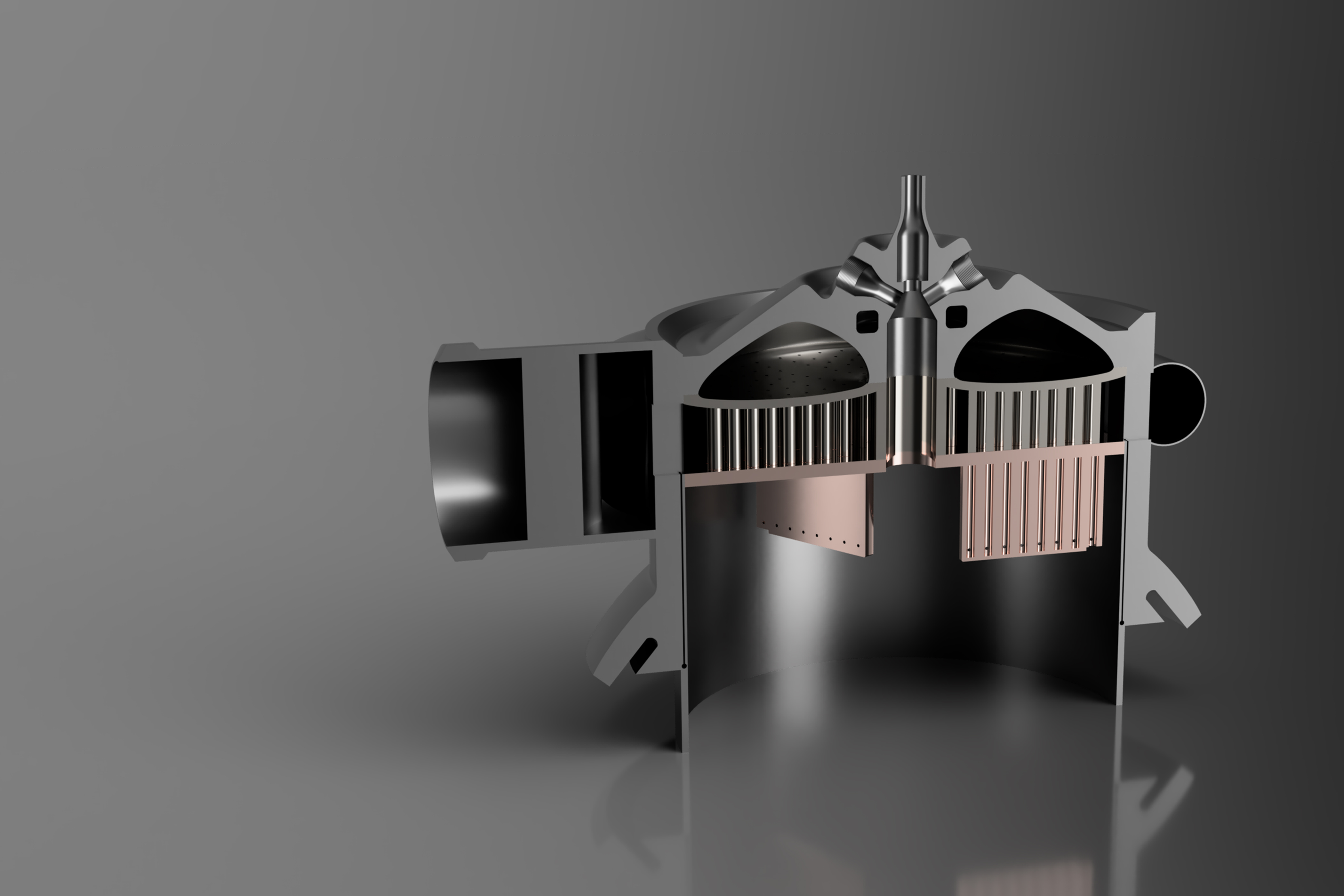
The baffles and the faceplate are cooled by hydrogen flowing through drilled holes into the combustion chamber. The outer structural body is cooled by the hydrogen flowing between the liner and the combustor wall (concentric cylindrical liner).